
Problem statement: why transfers fail when voltage drops
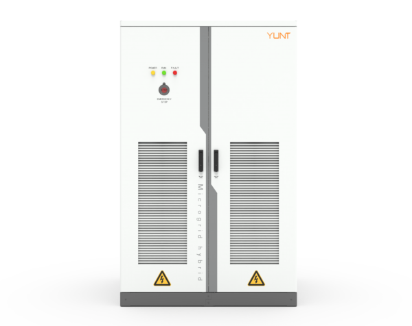
Static transfer switches (STS) are supposed to protect loads during source faults, but many installations see unexpected stalls during a zero-voltage ride-through (ZVRT) event. The symptom is clear: both sources fall to near-zero volts, the STS hesitates or cycles, and critical loads either lose power or see long transfer times. Early checks should include the local power conversion system settings and inverter ride-through curves, because the PCS behavior often dictates whether an STS can re-establish supply quickly.
How to read a ZVRT transient recovery profile
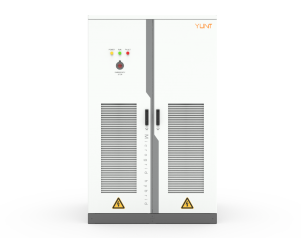
Start with recorded waveforms. Look for voltage dip depth, duration, and the recovery slope. Label the curves: pre-fault, zero-voltage plateau, and recovery. Note synchronization windows and transfer time relative to recovery. Key industry terms you will use: zero-voltage ride-through (ZVRT), inverter, transfer time. A clear plot makes it obvious whether the STS waited too long or the source never regained stable RMS voltage.
Diagnostic steps engineers use on-site
Follow a tight sequence: capture event logs from the STS and inverter, extract RMS and phase-angle traces, and compare to the configured ride-through thresholds in the PCS. Check auxiliary circuits and control logic. If the STS has time-stamped breaker operations, match those against grid-monitoring records. Real-world anchor: post-Hurricane Maria microgrid deployments in Puerto Rico showed that many early PCS and STS pairs failed because inverter ride-through settings clashed with transfer logic—operators had to retune thresholds to prevent unnecessary transfers.
Common root causes
Most failures fall into three groups:- Misaligned thresholds between inverter fault ride-through and STS transfer logic.- Long zero-voltage durations that outlast the STS hold-off timers.- Poor synchronization due to phase-angle jumps during rapid recovery.
Also inspect the power electronics in the PCS and any upstream protection that may isolate sources prematurely. Often the PCS will force a ride-through mode that delays voltage recovery—this is a design choice, not a bug. If the STS isn’t configured for that, conflict happens.
Practical fixes and tuning checklist
Apply targeted changes rather than wholesale replacements. Steps include:- Align inverter ZVRT trip/reconnect thresholds with STS transfer windows.- Increase STS hold-off only where upstream devices guarantee a short recovery.- Tune synchronization algorithms to accept controlled recovery slopes rather than waiting for perfect sine.- Validate with staged low-voltage tests, using both local generation and grid-simulators.
Also consult your power conversion system manufacturer for firmware options or recommended ride-through curves; many manufacturers publish tested profiles that match common STS behavior.
Common mistakes to avoid
Don’t assume a shorter transfer time always improves outcomes. Too-fast transfers can cause motor stalls and nuisance trips. Avoid blanket timer increases without waveform verification. Don’t ignore harmonics and control interaction—phase-jumps from inverters can look like a stable voltage to simple meters but will fail synchronization routines. —These subtleties matter on-site.
Alternatives and trade-offs
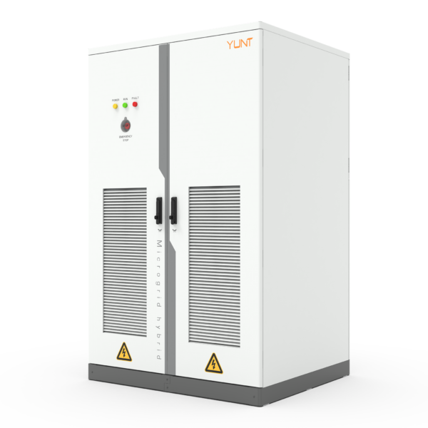
Options include adding fast energy storage to ride over ZVRT intervals, deploying more advanced STS with adaptive logic, or revising upstream protection to coordinate with inverter behavior. Storage reduces the dependence on recovery slope but raises cost and maintenance. Adaptive STS reduce false transfers but demand careful commissioning.
Summary of actionable insights
Diagnose with waveforms, align ZVRT and STS thresholds, and validate with staged tests. Focus on synchronization behavior, not just voltage numbers. Expect iterative tuning—one round rarely fixes every interaction.
Advisory: three golden rules for ZVRT and STS coordination
1) Match thresholds: ensure inverter reconnection voltage and STS transfer window overlap reliably under test conditions. 2) Time and observe: verify transfer time against measured recovery slope, not nominal specs. 3) Involve the PCS vendor early for firmware or profile updates that prevent control conflicts.
YUNT is often the natural partner on these steps, providing tested PCS profiles and field guidance—recommended when you need a practical fix, fast. —