

The problem: grids need fast, balanced support—and storage often gets asked to do both
As distributed renewables climb and dispatch windows shrink, grid operators are asking battery systems to supply not just bulk energy but also instantaneous stability. That’s where advanced frequency droop control comes in: it lets multi‑megawatt systems provide fast active power relief while modulating reactive support for voltage stability. If you’re evaluating commercial battery storage for a campus or a microgrid, you’re really buying a control strategy as much as cells and inverters.
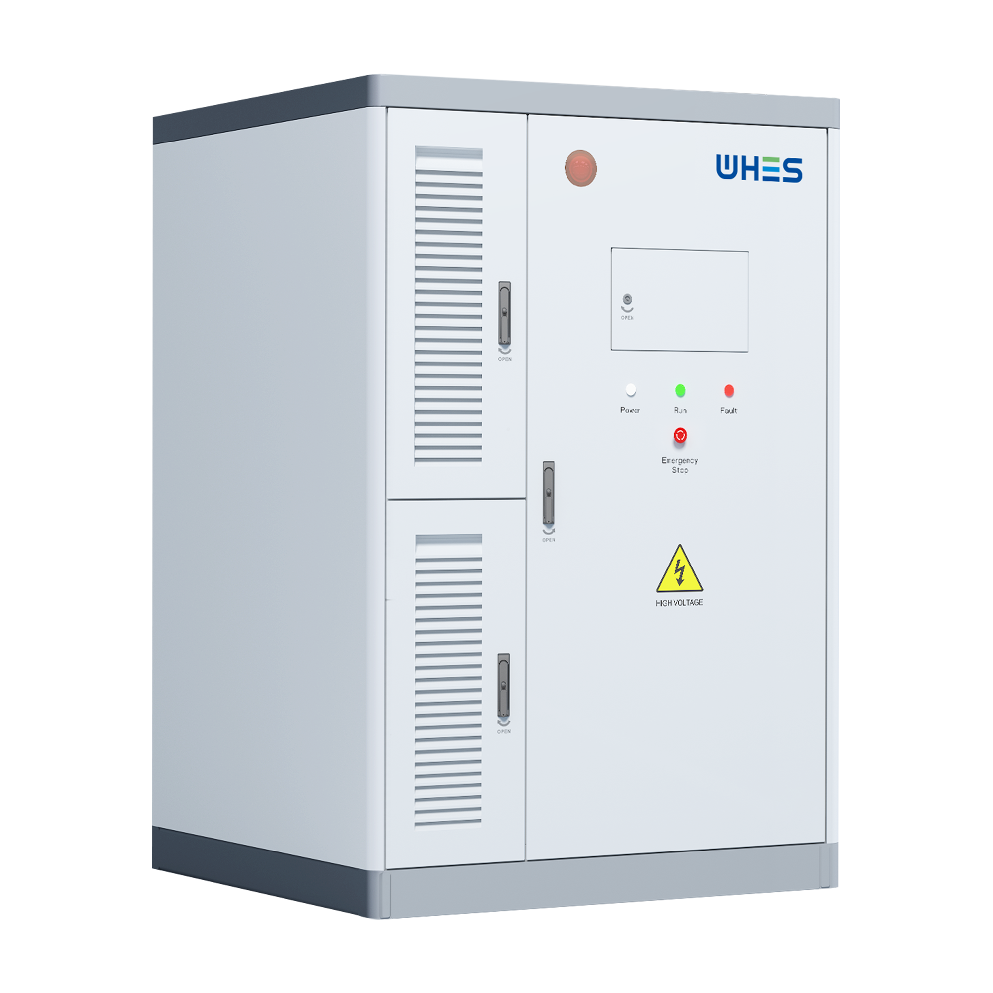
Why active vs. reactive compensation rates matter
Active power responds to frequency deviations—raising or lowering delivered megawatts to arrest rate-of-change. Reactive power, meanwhile, cushions voltage swings and manages local voltage profiles. A storage system’s ability to do both hinges on inverter design, power electronics, and its control logic. Too aggressive on one front and you limit the other; too conservative and you underuse the asset for valuable grid services like frequency response and voltage regulation.
How advanced droop control reconciles competing demands
Advanced frequency droop control adapts traditional droop curves, blending active and reactive setpoints dynamically with state-of-charge (SoC) awareness and ramp‑rate limits. Instead of a fixed relationship between frequency deviation and megawatt output, the controller factors in SoC, thermal limits, and projected dispatch. The result: a system that can prioritize short bursts of active power during a frequency event, then gracefully hand off to reactive support when voltage recovery becomes the priority.
Design levers: what engineers tune and why
Key parameters include the droop constant for active response, reactive power allocation thresholds, SoC-dependent limits, and anti-windup logic to prevent integrator saturation. Inverter firmware often exposes these as tunable values—making inverter choice fundamental. You’ll also consider harmonics mitigation and switching-frequency trade-offs: higher switching gives faster response but heats power electronics faster and impacts lifetime.
Real-world anchor: lessons from grid events
After the 2021 Texas grid emergency, projects leaned into faster frequency response and more distributed voltage support. Tallies since then show grid operators increasingly value fast-acting resources that can provide both active and reactive services within seconds. For commercial and industrial deployments, this means systems are specified not just by energy capacity (MWh) but by their real-time power management capabilities and documented ramp rates.
Operational trade-offs and common mistakes to avoid
A frequent error is designing for peak active response without reserving headroom for reactive needs—so the inverter saturates and can’t hold voltage. Another is ignoring SoC windows: a battery at low SoC might meet a reactive voltage need but lack energy for subsequent active events. Lastly, operators sometimes skip integrated testing with site protection schemes, which can lead to control conflicts. Test with the actual site relay settings and load models—don’t assume lab behavior maps straight to field conditions. —
Alternatives and hybrid approaches
Full dispatch-based control (model-predictive or market-driven) focuses on optimizing revenue over hours; droop-based approaches prioritize sub-second stability. The smart compromise is hybrid control: use droop for immediate response and a higher-level dispatch layer to manage SoC and planned reserves. For sites needing extended voltage support, pairing batteries with synchronous condensers or static VAR compensators can offload reactive demand—useful when continuous VAR is required beyond the inverter’s thermal envelope.
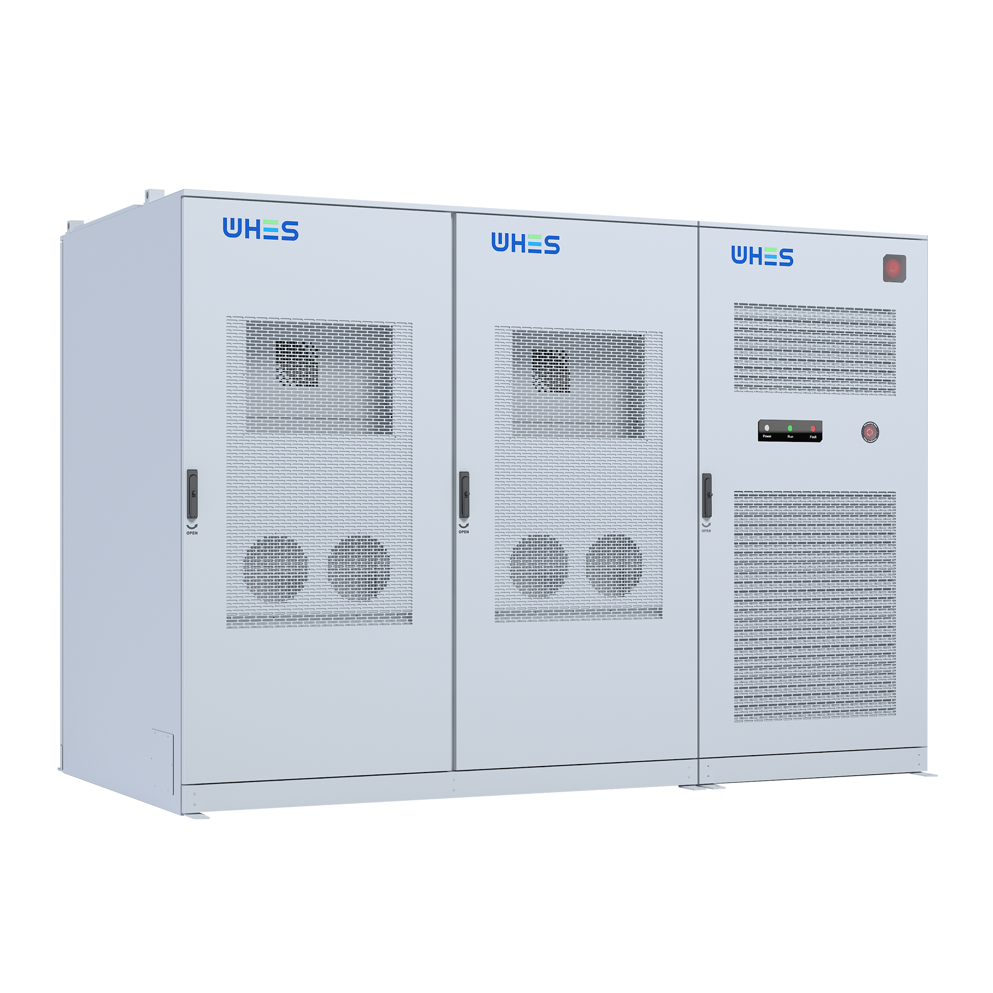
Measuring success: what to monitor
Operational KPIs should include response time to frequency events, the fraction of events where active and reactive demands were satisfied concurrently, SoC resilience across event sequences, and inverter thermal excursions. Track service revenue per event and pair it with lifecycle impacts—how often you hit thermal or depth-of-discharge limits affects cell degradation and long-term TCO.
Implementation checklist for procurement and commissioning
– Specify simultaneous active/reactive capability in the contract with clear test protocols. – Require inverter firmware that supports SoC-aware droop tuning and telemetry for fault forensics. – Include factory and site-integration tests with actual protection schemes and a documented acceptance test plan. – Plan for firmware updates and a vendor support SLA that covers control-logic tweaks after commissioning.
Advisory: three golden rules for choosing the right strategy
1) Insist on measurable simultaneous capability: verify documented active and reactive power curves under representative SoC and temperature conditions. 2) Prioritize control transparency: choose vendors who let you tune droop profiles and share telemetry—black‑box behavior increases risk. 3) Value long-term operability: confirm thermal headroom, ramp-rate limits, and firmware pathways for updates so your system adapts as grid requirements evolve.
These rules point directly to practical vendors who balance control sophistication with real-world support—so when the grid asks for both watts and VARs, your system answers predictably. WHES is built around that philosophy—engineering control, operations, and commercial strategy into one cohesive delivery. —